I’ve been tinkering around a bit with some Raspberry Pi devices for a number of little projects. Most have been related to home automation type stuffs, but I built one with a 7” screen that I was going to be using for radio related things. Originally I had tossed together a small kit with an SDR for use on a camp because I knew we’d be out of range of cell phone service, but knew I could still take advantage of radio frequencies from satellites to get data, specifically weather images.
All seemed to go quite nicely, however I’d sporadically get a lightening bolt in the top right corner of the screen. I later learned that was a sign that the Pi wasn’t getting enough voltage. This baffled me, I was using a decent 5v power source, why would I get a low voltage issue? So I decided to do some research.
For the uninitated, a Raspberry Pi is a single board personal computer. The best place to get a lot more information on the Pi is the official website. For this post, the bits we’re most interested in is the power requirements. All models of the Pi use a 5V (5 volts) input via a USB-B Micro connector, the ones used on most cell phones. The bit that varies from model to model, and attached peripherals, is the amount of power required to drive them (see here for a breakdown). For example, a Pi 3 Model B+ can draw as little as 500mA (500 milliamps) or up to 1.2A (1.2 Amps or Amperes). Most cell phone chargers can supply that kind of power fairly easily now. If you look at your Samsung charger that comes with an Samsung Galaxy S8+ for example, it has an output capacity of 2A. So, this would make one think you could just grab your cell phone charger and use it to power a Raspberry Pi, right?
Absolutely! So why am I writing this blog post? And why does the Pi report “Under-voltage” if a cell phone charger can deliver the required power? First let us take a look at what the issue looks like. When you have a screen attached to your Pi, you’ll see something that looks like this
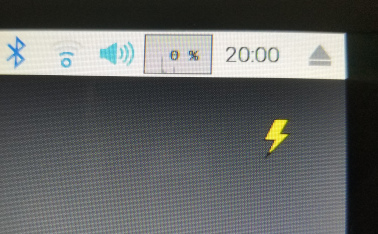
If you run dmesg or if you look in /var/log/syslog you may see something that looks like this:
[ 2.071618] Under-voltage detected! (0x00050005)
I usually see this appear after I start the Pi up, or if I’m doing a lot of processing on it.
So what causes the suitably powered cell phone charger to not be able to deliver the required juice to the Raspberry Pi? It’s actually not the charger itself, but how you connect to the charger. This is where a little high school physics / electronics comes into play.
If you’re tinkering with the Raspberry Pi, I’m going to assume you’re probably familiar with at least some basic contepts of eletronics, but the Law we’re going to talk about is Ohm’s Law. Ohm’s Law states that the current through a conductor between two points is directly proportional to the voltage across those same two points. The ratio of voltage to current is called resistance. This is where we get into material sciences, wire gauges, and specifications.
To save reading through all the specifications, I’m going to tell you that a USB cable is supposed to use 28 to 20 AWG (gauge) for the power lines1. If I grab one of my USB cables, the total diameter is 0.120” or 3.05mm. In that space, you have to fit 2 28-20 AWG lines for power, and 2 28 AWG for data/signal. They also have to be covered so they don’t short each other, and then all covered completely to stop the 4 wires just hanging out everywhere. Keep these numbers in mind.
Now we’ve talked about the size of the cables, let’s talk about the materials. Copper is expensive, so if a company can reduce costs slightly, you’re likely to find those power lines are on the smaller side such as 28AWG. All materials have a resistivity, even if it’s some crazy high number. In terms of Copper it is about 1.72x10⁻⁸ Ωm. You can see more examples on Wikipedia here. If you don’t recall what x10-8 or e-8 means, it is a fancy way to say “move the decimal place 8 spots to the left and saves you writing a lot of zeros. This is a tiny number, but it does have an impact. This is where Voltage Drop comes in. Voltage drop says that the voltage is reduced as current moves through an electrical circuit. Voltage drop is calculated, in DC circuits, using a similar formula to Ohm’s Law, except we’re calculating over the length of the entire wire 2.
\[V_{drop(V)} = I_{wire(A)} * R_{wire(\Omega)}\]So we need to know the resistance of the whole wire, which is calculated using:
\[R_{total} = 2 * R_{wire} * L_m / A_{wire}\]So resistance of the total wire is 2 times the resistance times the length divided by the area.
\[A_{wire} = \frac{\pi}{4} \times d^2 \\ d_{wire} = (0.127e^{-3})_m \times 92^\frac{36-n_{gauge}}{39} \\ d_{wire} = 0.000127 \times 92^\frac{36-28}{39} \\ d_{wire} = 0.000321m \\ A_{wire} = \frac{\pi}{4} \times 0.000321^2 \\ A_{wire} = 8.097e^{-8} m^2\]Now to drop it all together.
\[R_{total} = 2 \times 1.72e^{-8} \times 1.8288 / 8.097e^{-8} \\ R_{total} = 0.77\]So the total resistance for 6’ (or 1.8288m) of copper is 0.77 Ohms. We have the current draw from the Pi, which is 1.2A. So what’s the voltage:
\[V = I R \\ V = 1.2 \times 0.77 \\ V = 0.932V\]So for the total length of the wire, there is a drop in voltage of 0.77v, or about 15.4%. So a 5v input on 6’ cable becomes 4.23v at the end, and this is in the danger zone for the Pi to be operating.
So how do they (Pi Foundation) get around this? Well their suggested power supply uses 20AWG wire, and it’s about 1.5m long, and doesn’t deal with the signal wires. So lets do using the above formulas again, it only has a voltage drop of 0.16v, or about 3.19%, keeping the power at the Pi above the threshold to generate errors. There are other similar power supplies by other vendors that also use the same setup, like Cana Kit, or the official one. It’s worth noting some kits ship with regular USB cables, which might work for some of the Raspberry Pi line, but you have to be aware of the limitations of the cables.
The TLDR3 of this is that voltage drop across small gauge wires is killing your voltage at the Pi.
Quick thanks to @press5 for a review of the post before I posted it.
-
This is important to remember. The smaller the number, the larger the diameter of the wire. So a 28 AWG wire is 0.0126” or 0.321mm, while a 20 AWG is 0.0320” or 0.812mm. ↩
-
If you don’t want to read all the formulas and math, there are voltage drop calculators such as this that work nicely. ↩
-
Too Long, Didn’t Read ↩